Polyphonic FM Synthesizer with STM32F031
06 Dec 2015
Hi All,
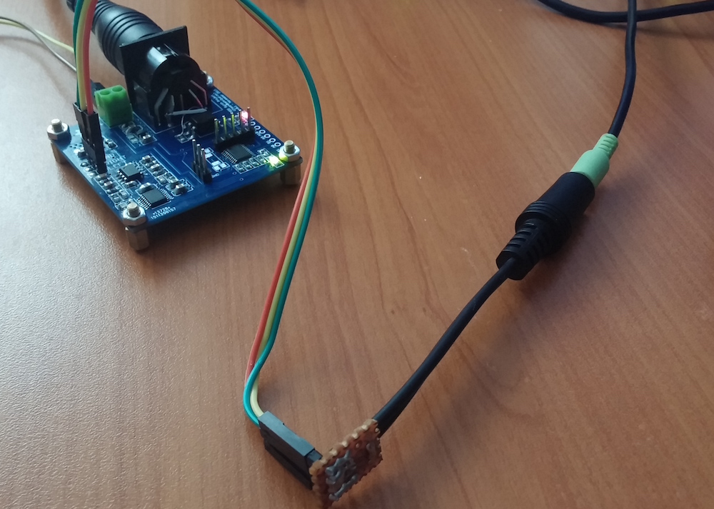
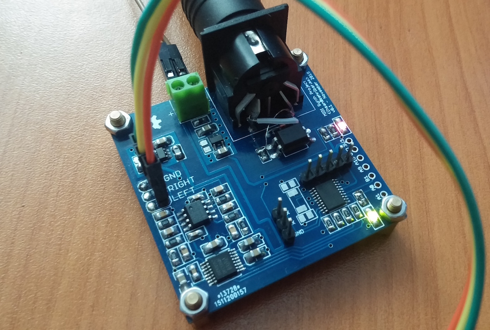
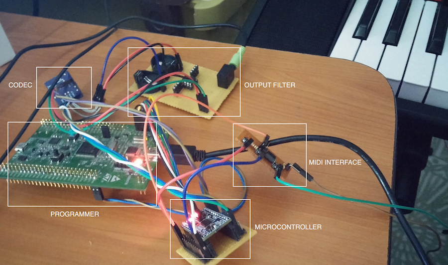
I’ve built a playable, MIDI capable, polyphonic FM synthesizer using an 32bit ARM Cortex M0 microcontroller and an audio codec. This was a learning experience for me. You can find the finished form of the system in following two images.
Sound samples for the system can be found from the following two links.
- https://soundcloud.com/ihsankehribar/wandering
- https://soundcloud.com/ihsankehribar/daft-synth-stereo (Midi notes are coming from computer)
Please note that, there is no single tone for this device. Almost every parameter is tunable on the fly. In the future I may build a user interaface with buttons and knobs for this device but at the moment I’m just following change software - recompile - burn path for creating different sounds. Not much effective but works at the moment. :)
Earlier Work
Couple of months ago, I started this idea of creating a synthesizer with Atmel’s Xmega32E5 8bit microcontroller. You can find the code base for this project from here: https://github.com/kehribar/xmega_fm-synth
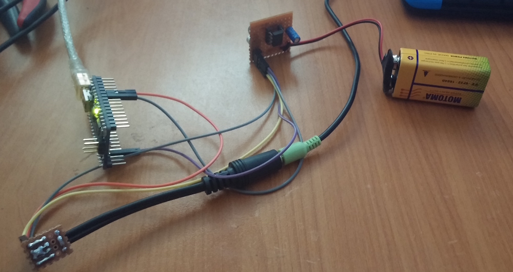
I hit some limitations with the Xmega system and wanted to go with an 32bit microcontroller. I ordered / designed couple of breakout boards and before moving on the final PCB form I prototyped the system.
Schematic
Final schematic is below. I’m going to explain the system part by part.
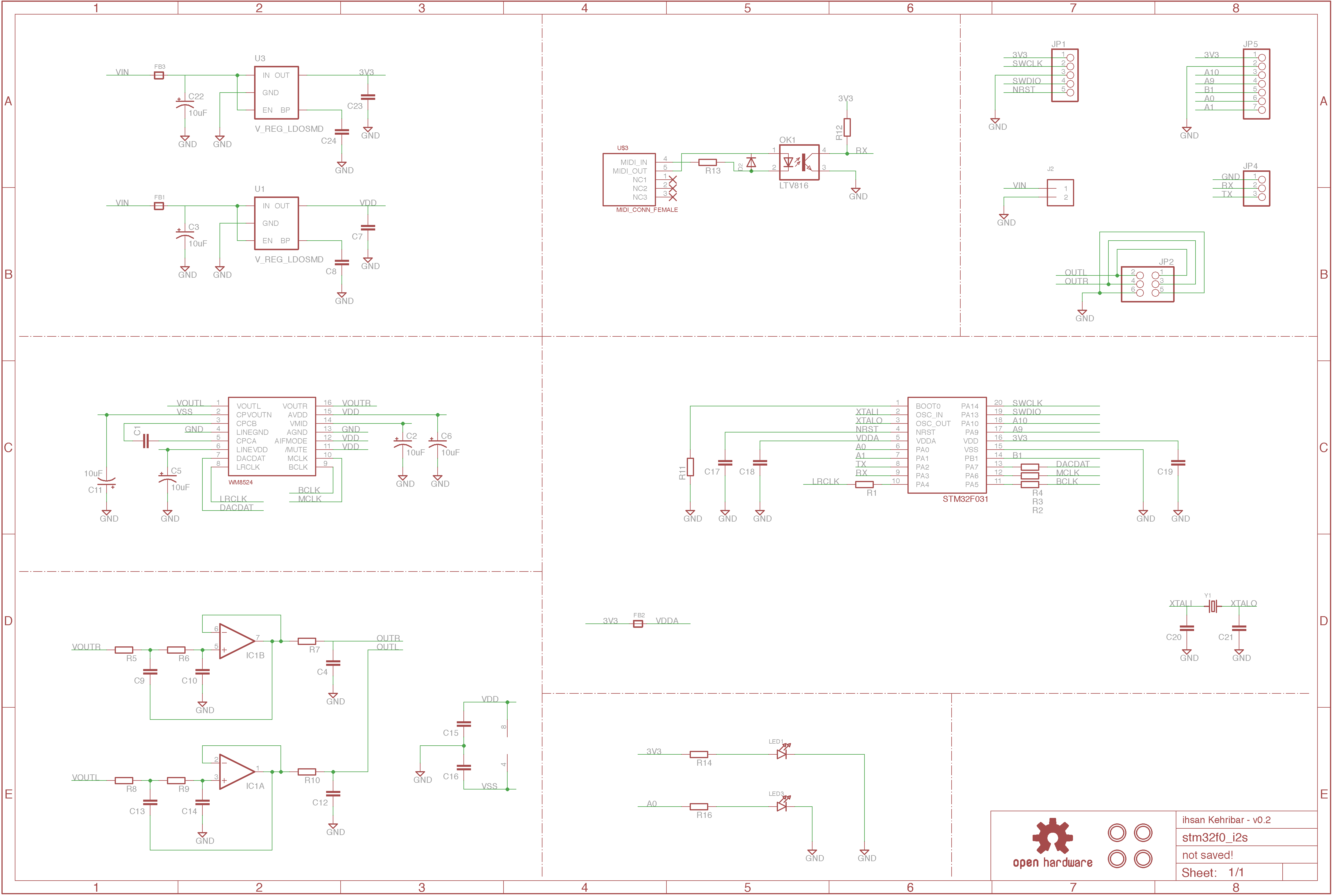
Microcontroller
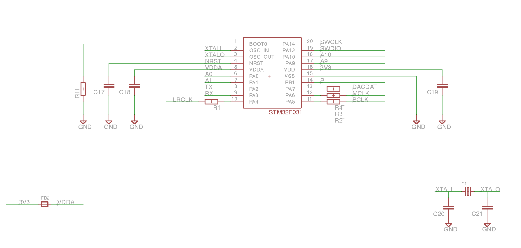
I used an ARM Cortex M0 core STM32F031 for the project. Cortex M0 cores don’t have anything really extra than having a 32x32 hardware multiplier for DSP purposes. Cortex M3 and M4/M4F have specific DSP instructions and they would have been much more helpful for such a computational intensive task, but I just wanted to try what can be done with a low cost, entry level ARM chip. That specific microcontroller also have I2S and DMA module which is essential for this project.
For the system clock, I’m using the internal PLL to generate 48 MHz clock but I left optional XTAL footprint for future possible use.
R1,R2,R3 and R4 is used to slow down the edges of I2S signals to lower the high frequency noise a little bit. I put 49.9 ohms in the real circuit.
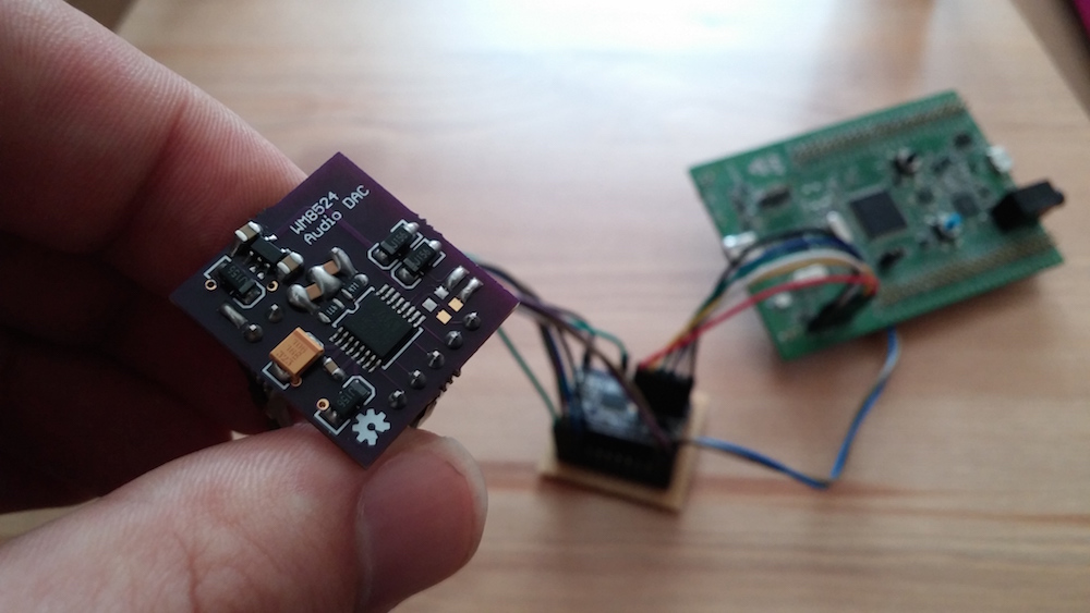
Audio Codec
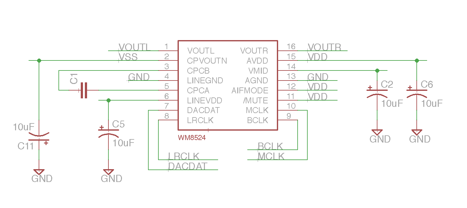
This is 2channel, 24bits, 192kHz sampling frequency capable audio DAC from Cirrus Logic (previously Wolfson).
Best thing about this codec is, there is no need for DC blocking caps on the output. That means first of all no need for big bulky capacitors and secondly low frequency response of the output is much better since there will be no need for a high-pass filter to remove the DC level.
Also, this codec generates a negative bias voltage via internal charge pump and I’m tapping that voltage from the codec to power the opamp’s negative supply.
Output filter
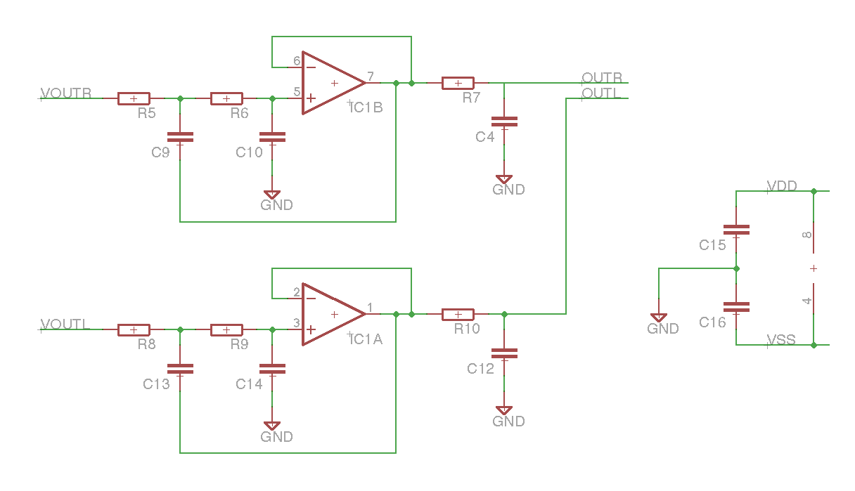
Opamp that I used is MCP6002. It is not a low noise or audio grade opamp but it is rail to rail input/output and have enough bandwith and noise level for a just voltage follower.
This is a second order Sallen Key low pass filter followed by a single order passive low pass filter. Component values should have been properly selected for the best rejection curve, but I used 4.7 k for resistors and 4.7nF for the capacitors which gives roughly 7.3 kHz -3db point.
Power supply
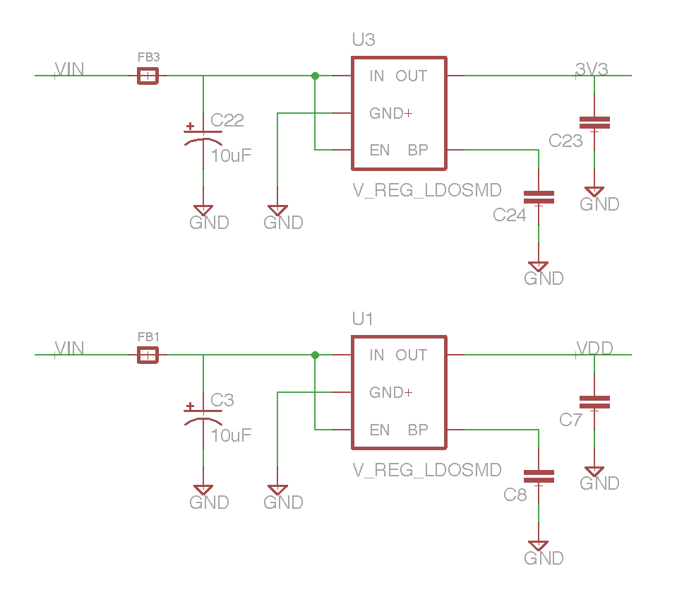
LDO footprint is compatible with generic 5 pin SOT23 LDOs. Specifically I used Micrel MIC5317. There are two seperate regulators, one for the microcontroller, other for the codec + output filter. There are also ferrite beads at the input stage of the LDOs to filter out some high frequency noise as much as they can.
Midi interface
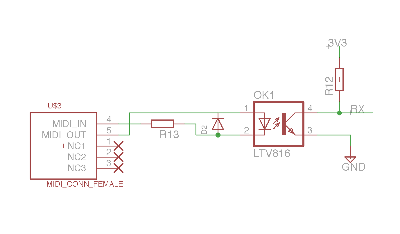
Optocoupler decouples the instrument ground with the controller board ground and eliminates possible ground loop issues. Also, optocoupler acts as a voltage level conversion between whatever MIDI keyboard sends and 3V3 microcontroller level.
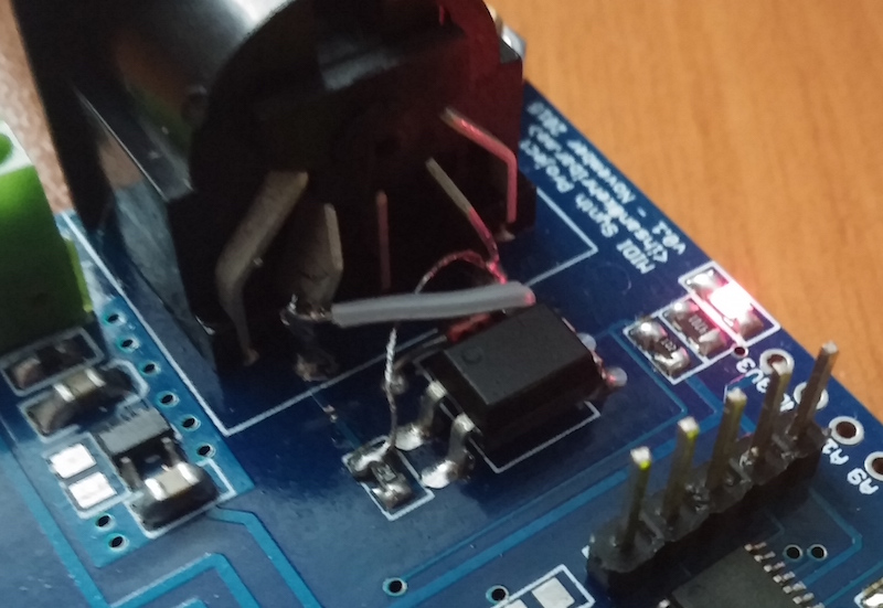
In the v0.1 hardware, I mixed pin#4 and pin#5 of the connector. I patched it with knife + patch wires on the PCB. Easy mistake! :) Schematic is corrected.
Layout
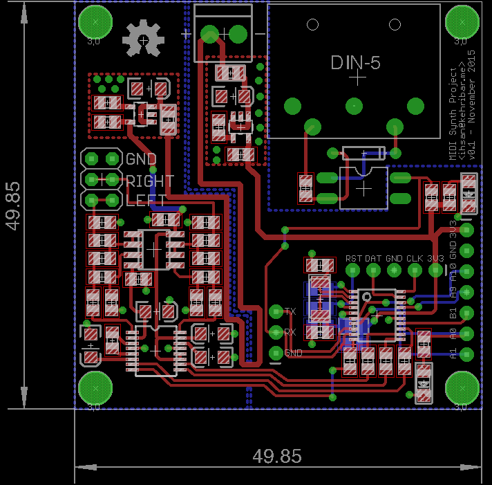
I tried to follow Henry Ott’s advice for this layout. You should read his excellent article on the topic. http://www.hottconsultants.com/techtips/split-gnd-plane.html
I partioned the analog and digital portion of the layout seperate and connected two portions over a small bridge and passed every neccessary signal between two portions only on top of that bridge.
Sizewise, I just sticked to 5x5 cm rule of the low cost PCB fab houses though it could have been smaller if needed.
I used http://dirtypcbs.com/ for the PCB manufacturing.
Firmware
Toolchain
GitHub repository for the firmware is this: https://github.com/kehribar/stm32f031_template/tree/master/_synth This particular firmware is a part of my trial on creating a generic framework for STM32F031 microcontroller. You can check the base repository for other examples.
I used GCC compiler that I downloaded from http://launchpad.net/gcc-arm-embedded. Telling the Makefile where you unzipped the toolchain is enough. For the programmer, I used an STM32F4 Discovery board. After removing two jumper headers, that board acts like a generic ST Link v2 programmer. Calling make iterate on the command line just recompiles everything and flashes the board via OpenOCD under 10 seconds.
Sound synthesis
For a proper background on the topic, you can read about FM synthesis from the following links. I won’t be able to explain better :)
Here is my quick notes on the sound synthesis details of the system. You can also read the firmware to get more idea.
- Sampling rate for the system is ~48 kHz.
- All calculations are done with 16bit operations and all of the sounds are summed up to 24bit at the final stage with no loss of resolution.
- System has 8 note polyphony at the moment. System can work with even more than that, but I limited it with 8 for the time being.
- System has an LFO that modulates the amplitude of the sound at the final stage to create a tremolo like effect.
- That amplitude changing LFO has also stereoPanning_offset variable that controls the automatic stereo panning effect between left and right channels.
- There is one additional LFO to modulate the signal phase at a constant frequency with its own separate envelope to enrich to sound.
- In total, there are three diffent envelopes, for output amplitude, fm modulation amount and lfo modulation amount for each sound with adjustable attack, decay, sustain and release parameters.
- System is touch sensitive, meaning that maximum sound level and FM modulation amount changes with the velocity of the MIDI note.
DMA
DMA is used to transfer data from the microcontroller to codec. DMA on the STM32F031 isn’t double buffering capable so I had to trick the system to emulate a double buffering.
DMA itself has Transfer Complete and Half Complete interrupts. In the while(1) loop, I poll for these two interrupt flags and fill the first half or second half of a fixed lineer buffer based on which flag is set. As far as DMA concerns, it wraps to the begining of the array after it goes to end but in the mean time I change the content of the buffer without any data corruption problems thanks to the indication flags.
I2S
I2S peripheral of the SMT32F031 supports 24 bits transfers but it doesn’t play well with the DMA. For each sample, first you need to shift the data 8bits to left align it to 32bits. Second, you need to swap the higher 16bits and the lower 16bits in that variable. It is most probably due to how the DMA reads the memory. I learned that by some amount of debugging session.
The following code sample fixes a 24bit right aligned signed data to proper format such that when DMA reads it, actual outcome is what you expect. So much for a low cost microcontroller. :)
static inline int32_t convertDataForDma_24b(const int32_t data)
{
  uint32_t result;
  uint32_t shiftedData;
  shiftedData = data << 8;
  result = (shiftedData & 0xFFFF0000) >> 16;
  result |= (shiftedData & 0x0000FFFF) << 16;
  return (int32_t)result;
}
Downloads
You can download the Eagle files for this project from the following links.
Licence
This project is published under the terms of the GNU General Public License, version 3 licence.
Acknowledgement
Mutable Instruments community was really helpful to me during the development of this project.
- http://mutable-instruments.net/forum/discussion/7247/custom-xmegae5-fm-synth
- http://mutable-instruments.net/forum/discussion/7472/custom-fm-synth-with-stm32f031
Best,
ihsan.