ESP8266 + xmega32e5 - Wireless Temperature Sensor
10 May 2015
Hi all,
Couple of months ago I built a wireless temperature sensor using my xmegaE5 breakout board and an ESP8266 wireless module.
Normally this type of task could be handled inside the ESP8266 chip entirely; but at the time I couldn’t create a decent toolchain setup and I went with using the module over AT commands via stock firmware.
It measures the ambient temperature using MCP9700 sensor and sends the data to Sparkfun’s phant.io server. I’m using imp.guru to visualize the data. You can find my data stream from this link. Also, you can find the latest complete xmegaE5 firmware for this project from this link.
When the microcontroller powers up, firmware checks the state of external push button. If the button is pushed, it goes to server mode; otherwise it continues with the client mode.
if(digitalRead(D,3) == LOW)
{
  server_mode();
}
else
{
  client_mode();
}
For server mode, device creates a predefined wifi network that others can join in. In this mode, client mode SSID settings and phant.io public/private key informations can be loaded into microcontroller’s EEPROM without any firmware modifications and without any external hardware required. For interactivity, xmegaE5 acts like a very basic web server that responds back to TCP messages coming from port 80. Let’s say the wifi module has 192.168.10.100 IP address in the server mode. Trying to browse to the following link …
http:\\192.168.10.100\s,fancy_ssid_name
… from a web browser, sets microcontroller to store the fancy_ssid_name as its SSID name for the client mode. SSID password, public/private keys for the data server also configured similarly.
For client mode, device tries to join the SSID with the information stored inside the EEPROM. Then, periodically reads the ADC, applies filter on the result and tries to send to Phant.io server with a particular private/public key stored inside EEPROM. If anything goes wrong in the process, like wifi being down or HTTP request taking so long, system makes a full reset to recover from it.
You can check the firmware for other details. I’m running this system on and off for about 5 months, and works OK without any major problems.
Notes:
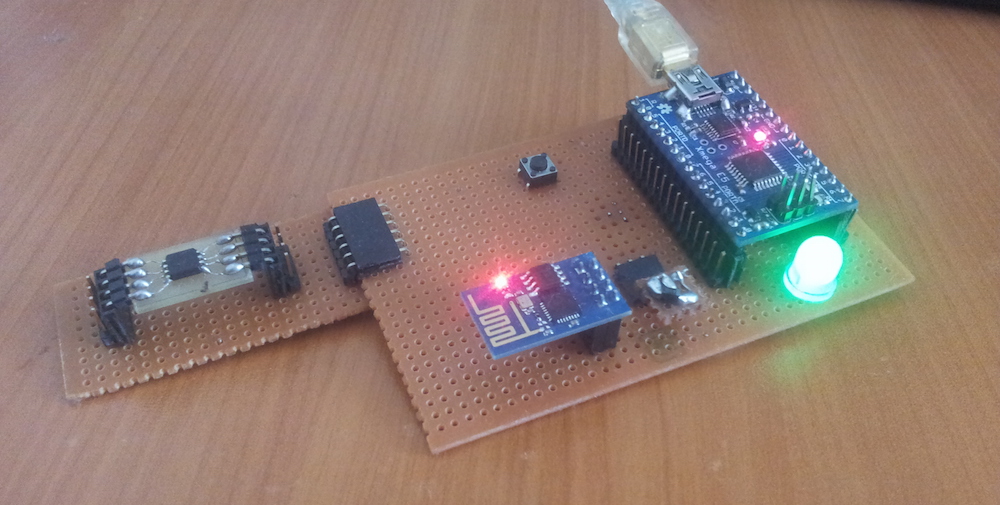
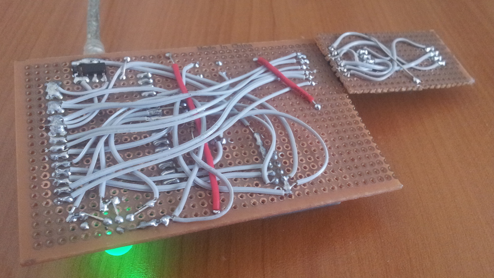
- There is an LM1117 LDO underneath the perfboard that generates a separate 3V3 rail only for the ESP8266 module from the 5V USB voltage. Onboard LDO of the xmega breakout board is not enough to power the wireless module properly.
- There is an RGB led for status indication and I’m driving it with a timer driven software PWM since I didn’t use the proper dedicated compare output pins.
- I also put a specific header for SPI flash IC and wrote a basic driver for it. Reason was to enable over-the-air programming support for the xmegaE5 chip. Since earlier I wrote a custom bootloader for xmegaE5 chip, firmware part wouldn’t be that hard but I couldn’t motivate myself enough to deal with proper cloud backend solution that can scale without any major issues.
- Firmware uses a lot buffers at its current state and could be reduced significantly with proper tweaks.
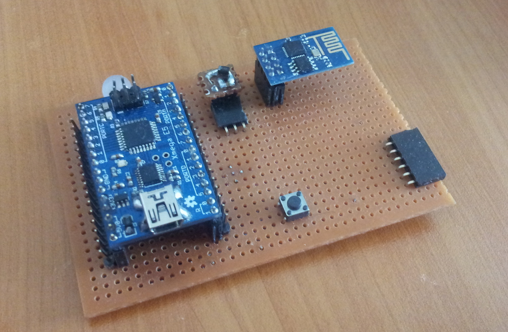
Here you can find couple more shots of the prototype: